To Boldy Go FORTH!

So, as mentioned earlier, I have installed FlashForth on an Arduino Nano.

In this blog I will tell you how I did it. There are some small things that make put you of on the track there.

Get the tools

To get the things going you will need:

  • Some Arduino board (Nano, Duemilanove, Mega 2560 R3 or Uno R3)
  • A way to get the hexfile on the board. I’m using a second Nano card with the ArduinoISP sketch and avrdude.
  • The code to burn. Can be found at Source Forge (Download link).

I am running Kubuntu, so the installation of avrdude is done by:

sudo apt-get install avrdude

Unpack the FastFoth archive and find the hex file needed. In my case

~/work/flashforth-code-537e623ec97a1f9c912eba7d6c7afaafbdd0c60d/avr/hex

Get a Programmer

If you allready have an ISP system, you can skip this part.

How to hook up two  Arduino Uno to use one as an ISP for the other is shown here.

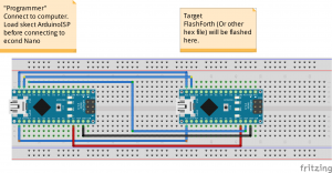
For two Nano, it is more or less the same:

PENTAX DIGITAL CAMERA

Or as a Fritzing sketch:

NanoISP_bb

 Program!

So, looking in the file “A Tutorial Guide to Programming PIC18, PIC24
and ATmega Microcontrollers with FlashForth” (found here.) I found a avrdude command to use:

$ sudo avrdude -p m328p -B 8.0 -c jtag3isp -P usb -e \
-U efuse:w:0xff:m \
-U hfuse:w:0xda:m \
-U lfuse:w:0xff:m \
-U flash:w:ff_uno.hex:i

Now, this line contains some errors for my setup. The easy ones:

I don’t use jtag3isp, I use avrisp. I have the programmer on /dev/ttyUSB0, not only usb.

There is one more problem. I don’t know if it is board, processor or programmer related. When I enter the line:

sudo avrdude -P /dev/ttyUSB0 -b 19200 -c avrisp -p m328p -v -e -U efuse:w:0xff:m -U hfuse:w:0xda:m -U lfuse:w:0xff:m -U flash:w:ff_uno.hex:i

I get an error:

avrdude: safemode: efuse changed! Was ff, and is now 7
Would you like this fuse to be changed back? [y/n] n

It seems my setup return unused bits in efuse as 0, but 1 is expected. Chaning the line to:

sudo avrdude -P /dev/ttyUSB0 -b 19200 -c avrisp -p m328p -v -e -U efuse:w:0x07:m -U hfuse:w:0xda:m -U lfuse:w:0xff:m -U flash:w:ff_uno.hex:i

does the trick.

Start playing…

To hook up to the new toy to the computer, I use:

sudo gtkterm –port=/dev/ttyUSB0 –speed=38400 –delay=10 –flow=Xon

and now I have a Forth Arduino Nano.

More on FlashForth
SourceForge page


On the Matter of Size

When you write a more complex program that uses several libraries, you will sometimes run into a problem with that the sketch doesn’t fit in the Arduino. What to do?
You can find some ideas in the Arduino forum and elsewhere. Some ideas:

Your Own Code

Do you need all those libraries? Really? Check again.
Rewrite your code. Do you make the same 4 line code snippet in several places? Use a function. With some good comments, it will not be more difficult to read your code.
Also, try different approaches. Since the compiler uses a optimizer, the result might not be what you think.

Variable Types

Floats are often bloats… Do you really need floats? Or can you handle it with a integer that is 10 or 100 times the float value?
Remember that RAM is even more scarce than flash memory on the Arduino, and integers normally takes less memory than floats in Ram also.


Libraries Blues

Libraries are a good thing. You don’t have to care about the details how to handle a DHT11 or DHT21.
But they are also a bad thing for flash. There are a couple of DHT libraries out there. Some are specific DHT11, some handle DHT11 and DHT21. If you only have one of them, maybe you should go for the specific version.
To minimize the size of the code, you could be helped by reading the documentation and code. Some libraries (like uTFT library) have defines to remove unused parts.
If this is not enough, you might have to rewrite the library yourself. See this text about that.

For instance, the uTFT library uses floats and doubles to draw lines. This should be possible to work around, and save some 2kB of flash.

The Arduino Dev Kit

This is a part I didn’t expect would give me headache…
But look at these three outputs:
Binary sketch size: 27 526 bytes (of a 30 720 byte maximum)
Binary sketch size: 32 130 bytes (of a 30 720 byte maximum)
Binary sketch size: 32 150 bytes (of a 30 720 byte maximum)
This is the output from three versions of the dev kit. (1.0.5+dfsg2-2, 1.0.5, and 1.0.6).
Now, for this problem, I have so far not found a good solution. In other types of SDKs you normally can change the parameters sent to the compiler, but with the Arduino kit it isn’t that easy. I also suspect that one or more library has been ‘improved’, but this type of improvement is not needed by me.
As you can see, it is a quite big difference also, more than 4 kB.

Not using c/c++

I have an Arduino Nano with FlashForth installed. This might be a solution also. See more in an upcoming blog entry…

Fail! Redo! Or you better know your toys.

I was a bit upset last night. I couldn’t get my DHT11 to work. Tried several libraries until I got the idea (through a forum post) that I should use the old multimeter. Ahh, the power rails on my breadboard are split! After some rewiring everything is working.


Now I have a simple thermometer/hygrometer.

Next headache: the SD card acts strange. It just makes a loop of 256 lines of information, and I just can’t figure it out… Another program writing to SDcard, using the same library seems to work. Ah, well, debugging time then…

The toys are here!

So, the mail arrived with my new toys. Too bad the weather is supposed to be sunny for some time.

IMGP4563


Well, I have some interesting time ahead getting the Arduion copy to work with all the parts. At least the Nanocopy works.

Also the TFT screen is connected and checked. The good news: it works! The bad news: The UTFT library takes some 80% of the flash space in the Arduino. So I need to remove more things from the library to get space for the other libraries I need.

IMGP4566 IMGP4568

Hack libraries was actually something I was expecting to have to do, since most libraries seems to have some things more or less hard wired that is not always needed or wanted.

Now, the library I found that works with my screen is a modified UTFT ver 1.3. Current version is 2.7 (Here is the latest version), so I will stick with on old version for some time. My code is on Github as UncleBod.

Now I have to continue some library hacking…

What you get is not allways what you order, or Hacking Time!

I have still not got the complete delivery from China (I’ll tell you what shop in China when everything is tested).
Still, two things I got (well, 2 items of the same type) gave me some trouble. Two nice solar powered LED lights (30 white LEDs).

IMGP4520
The text said that they had a on/off button, but no. They turn on when the light on the solar panel goes down…
So, what’s my options? Send them back (and pay as much in freight as they cost) or doing it the hacker way, making them work as I want?
The hacker way, of cause!
Since the function indicated that the important stuff is in the solar panel, I opened one and found this:

IMGP4523

OK, maybe that PCB can be changed a bit…. Let us take a closer look:

IMGP4525

A quick schematics layout (not 100% proofed yet…)

skärmdump6

U1(WS01) and U2 (8205) are the battery recharge circuit. I will try to remember to come back to them in a later post…

What was interesting to me was how to get the LEDs to go on even if the solar panel has light on it. The answer was quite easy. Remove R1. Then Q1 is closed and Q2/Q3 will turn on the light. After that it was just a matter of placing an external switch on the cable.

(ToDo: Get a better picture of the schematics….)

For those interested I’ve added data sheets for the two ICs and a PDF of the schematics (Made in KiCAD).

LedLamp WS01 8205

The lamp in the shop…


You always make a false reading

That was what my colleague was told when he was at a seminar about  calibration.

The talker continued:

“What we will learn today is how to estimate how much off the reading is, and if it really cares.”

This is a truth you always must remember while making measurements. You can NEVER get an exact true reading. If you use the analogue inputs on a micro controller, you have several possible sources of the error.

1) The reference

2) The bit factor

3) The physics

First part is a difficult one. an ADC (Analogue to digital converter) is always using some sort of reference voltage. On an Arduino it is by default Vcc. But Vcc is not always a good reference point. If you use a USB power source the Vcc is 5volts plus/minus 0.25 volt. I.e. 4.75 to 5.25 volts. This span is quite big if you want an exact reading.

On the other hand, in your implementation, this might be totally acceptable. Still, it is good to be aware of this.

Second part, the bit factor. Arduino uses a 10 bit ADC. This means that every step is Vref/1024. If your Vref is 5.0 volt, every step will be 0.00488 volts. In most situations, this should be good enough, but still, it is not my choice.

But now, let us go back to the reference again. Say that what you want to measure is a voltage that is expected to be in the 100 mV region, and never go over 200 mV. In such a case you really should reconsider what Vref to use. If you use Vcc as Vref, your readings will be around  20 for your nominal 100 mV up to 40 for 200 mV. In this case, a Vref of 0.5 volt, or even 0.25 volt would be much better.

The physics, or what are you measuring part.

First a small thought. What are you measureing?

Whatever unit you put on the output, you are measuring a relative voltage. OK, I know, you say. BUT some sensors are actually generating a current that is propotional to the read value. This means you have to measure the voltage over a resistor. Now, resistors are normally high precision (anyonel else remember what the gold and silver bands meant as tolerance readings on the old hole mounted resistors?).

You will normally have 1% tolerance or less on your resistor. If you have the right equipment you can even measure the exact resistor used and get even lower. But still, even if you get down to 0.1% tolerance, it is still a tolerance you have to consider if it will impact your final reading.

Another thing is the error of the sensor. When you read the specification, remember that the tolerance in some cases is given as % of full reading. if the sensor has 1% of full reading and is specified to 100 degrees, you have an error of 1 degree plus whatever else etror you got.
One more thing about physics. Sometimes you want the sensor at some distance from the controller. In this case you must be aware that the cable in effect is a RC network. and an antena. In most cases this is no problem, but as the distance rises, the error rises. Also, having a stright 2 wire sensor cable next to a mains cable for several meters will give interesting effects.

Two types of errors.
An important thing with errors is what type they are. I’d call them constant or variable.
Typical constant error is a resistors tolerance. If you measure the resistor you can expect two things:
a value that is within the stated tolerance
the same value every time. you make the measurement
This means that if you use the resistor for a measurement, for instance in a voltage divider, you can use the measured (verified) value in your code. Of cause, you will need to change the code if you change the resistor.

Another place when you most probably have a (mostly) constant error is the USB supply to your system. It will most probably be the same error every time you use the same source (computer or adapter) to hook up the system.
Variable errors are for instance noise from power sources (typicaly 50 or 60 Hz). These errors are more difficult to handle. One way is to take the mean value out of 3 to 5 measurements. The danger here is if you have a system that makes the measurements in phase with the mains cycle, you will have the same error each time….

The plan takes form….

test_1

First part of the plan

So, this is the plan:


A MCU, a temperature sensor, a combined temperature and humidity sensor, somewhere to show the readings and some keys to press.
To have a logger, let’s add a RTC and a SD card reader.
Even if I have a development board with a 90S2313 (called Attiny2313 now) somewhere, it will not be good enough for the logger function. Not enough Flash.
So, after surfing round I decided for an Arudino Nano. One reason is that I found a place that sells it for a good price. That it has USB port is another reason.

My current want to shop list….

Nano V3.0 ATmega328P-AU Microcontroller Board With USB Cable
DS1302 Real Time Clock Module Board DS1302 Module With CR2032 Battery
DS18B20 Temperature Sensor DALLAS 18B20 TO-92 Encapsulation
1.8 Inch Serial SPI TFT LCD Display Module With Power IC SD Socket
9V Battery And Battery Buckle Snaps Deduction For Arduino
Digital Temperature Humidity Sensor Module Probe For HVAC Arduino 4pin

Parts ordered:

  • Nano V3.0 ATmega328P-AU Microcontroller Board With USB Cable (1 item)
  • 40pcs 20cm Male to Male Color Breadboard Cable Jump Wire Jumper (1 item)
  • DS1302 Real Time Clock Module Board DS1302 Module With CR2032 Battery (1 item)
  • DS18B20 Temperature Sensor DALLAS 18B20 TO-92 Encapsulation (1 item)
  • DC 4 Key Matrix Membrane Switch Control Keypad Keyboard Super Slim Pad (1 item)
  • 1.8 Inch Serial SPI TFT LCD Display Module With Power IC SD Socket (1 item)
  • Digital Temperature Humidity Sensor Module Probe For HVAC Arduino 4pin (1 item)
  • 560pcs 56 Values 1/4W 1% Metal Film Resistors Assorted Kit Set (1 item)
  • 9V Battery And Battery Buckle Snaps Deduction For Arduino (1 item)
  • 300 Pcs 30 Values 2pF To 0.1uF Ceramic Capacitor Assorted Kit (1 item)

I’ve got a plan!

Yea, I do. Not a really big thing. It is just getting back to electronics after some 10-15 years.

OK, I stumbled over Arduino a year back or so. Looked interesting. Even more, since I earlier had a project with a AVR chip going on at home (A hexapod, don’t ask…).

A while back I stumbled over a online shop selling Arduino copies for a very good price, so now I’m in negotiations with the wife about a small project.

The idea is to make a simple thermometer to our greenhouse. The basic first version is planned to log the temperature and humidity inside the greenhouse and temperature outside. (Future plans is to have it send the data to a central unit (we are planning a second small greenhouse, so two measurement units would be logical). Then add a GSM unit to get the data to the mobile, then add.. (OK, I think you get the idea).

The blogs on this site will be about the project, and some general rants about electronics, programming and measurements.